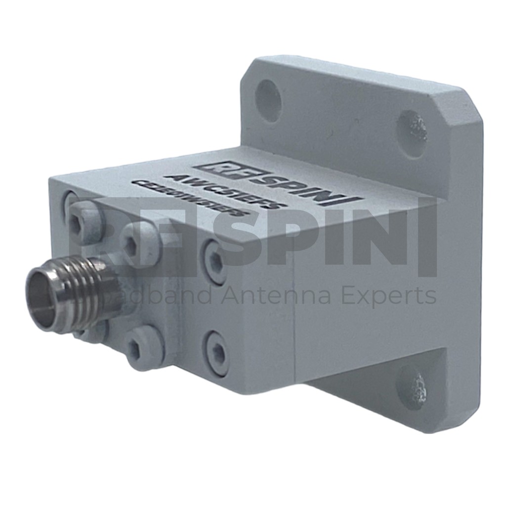
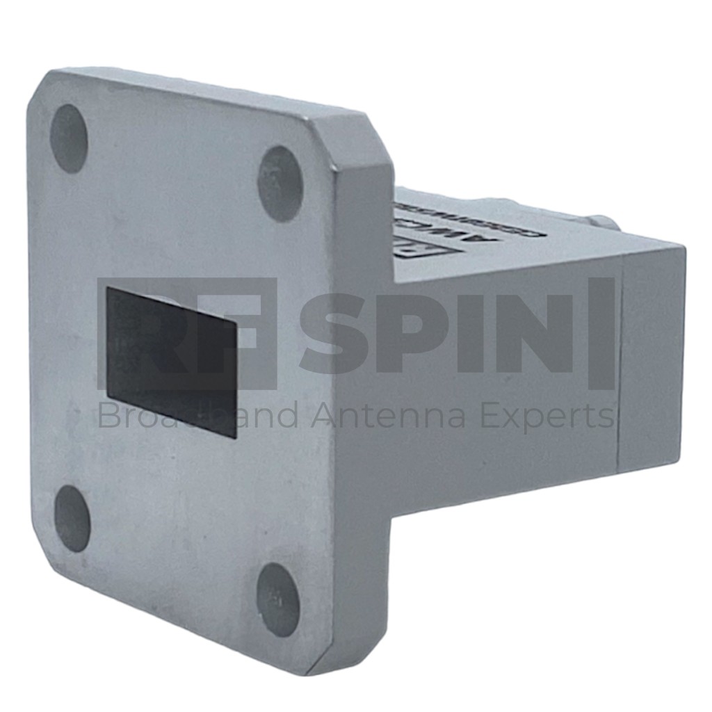
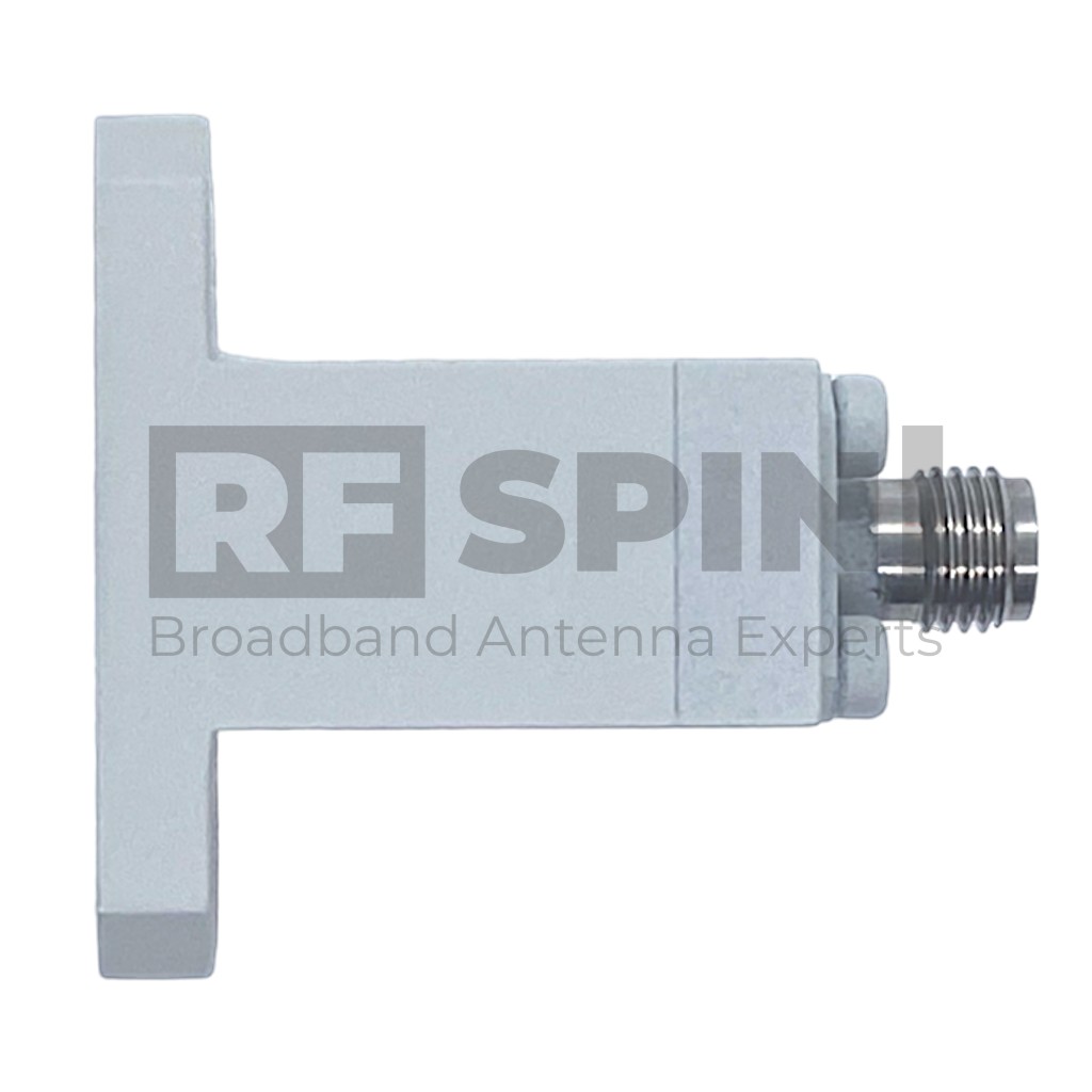
AWC51EFK Waveguide to Coax Adapter | 15 GHz – 22 GHz
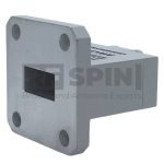
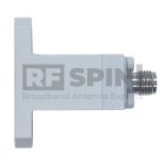
This Waveguide to Coax Adapter AWC51EFK is manufactured with an end-launch design. RF SPIN is using only high-grade aluminum and design with the fewest components to ensure top quality and superb performance. This AWC51EFK has waveguide size WR-51 and flange. Using a great quality 2.92mm female connector that is 50 Ohm is a matter of course.
Waveguide to Coax Adapter covers a frequency band from 15 GHz up to 22 GHz ensuring the extra performance of VSWR lower than 1.25 and low insertion loss.
Frequency Range
15 GHz – 22 GHz
VSWR (avg.)
1.15
Impedance
50 Ohm
Connector
K (female)
Power (CW / Peak)
15 W / 30 W
Select files to be sent by e-mail
Features and Specifications

Technical Performance
- Wide bandwidth
- Low return loss
- Individual calibration

Design and Surface Treatment
- Corrosion-resistant coating

Manufacturing Technology
- Manufactured using a high grade aluminum alloy
- Extremely durable
- High quality K type coaxial connector

Product Packaging Includes
- Waveguide to Coax Adapter
Product Parameters
Product identification
- Product Name AWC51EFK
- Product Category Waveguide to Coax Adapter
Electrical specifications
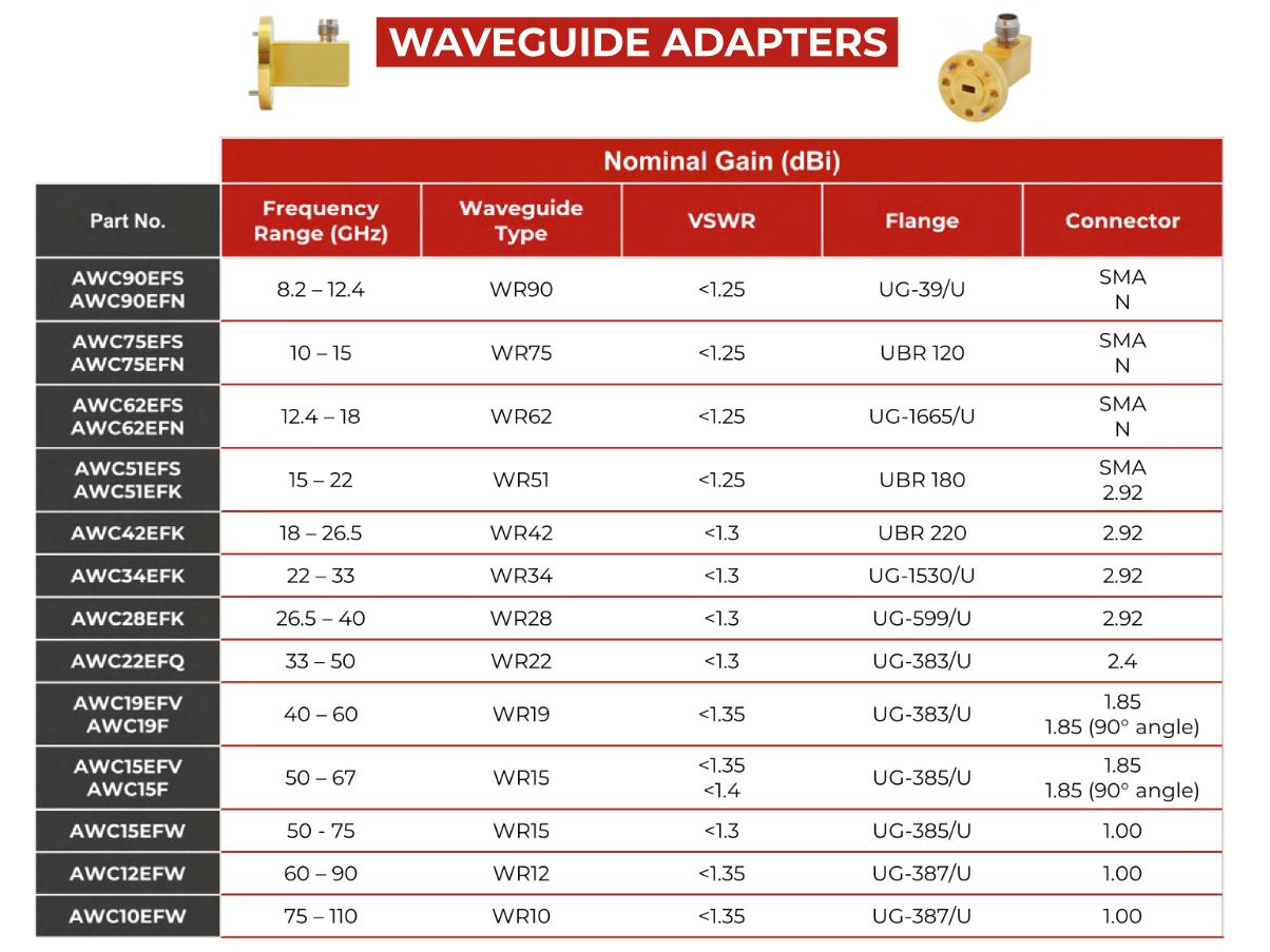
- Frequency Range 15 GHz – 22 GHz
- VSWR (max.) 1.25
- VSWR (avg.) 1.15
- Impedance 50 Ohm
- Insertion Loss (max.) 0.6 dB
- Connector K (female)
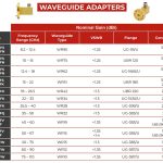
- Waveguide Size WR51
- Waveguide Flange UBR 180
- Power (CW / Peak) 15 W / 30 W
Operating conditions
- Rated Temperature Range 0°C – +50°C
- Storage Temperature Range -20°C – +70°C
Packaging and Accessories
What's in a box
- AWC51EFK Device
- Factory calibration certificate
- Full calibration report of each antenna
- QR code accessing online portal
- Calibration test dataset (available online)
Accessories
- Standard mounting flange
-
 Factory calibration report
Manufacturer Information
