Research Institute Solutions

Metrology, radio astronomy
and everything in between

Research institutes across that whole span already work with RF SPIN antennas.

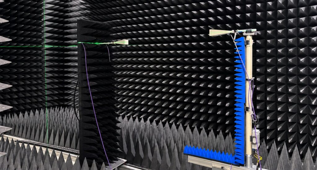
Ridged horn antennas facing each other in the RF SPIN anechoic chamber
Why RF SPIN

Two kinds of proof, and one company behind both

No unit ships without its own measurement, and our ISO/IEC 17025 laboratory, accredited by ČIA, can add a calibration where a result has to rest on one. Design and production never leave our hands: Prague and Nová Paka, in the heart of Europe.

Research settings

From bench to observatory

A horn that suits an antenna range may be the wrong choice on an outdoor mast. Each setting below asks something different of the antenna, and the models that answer it follow further down.

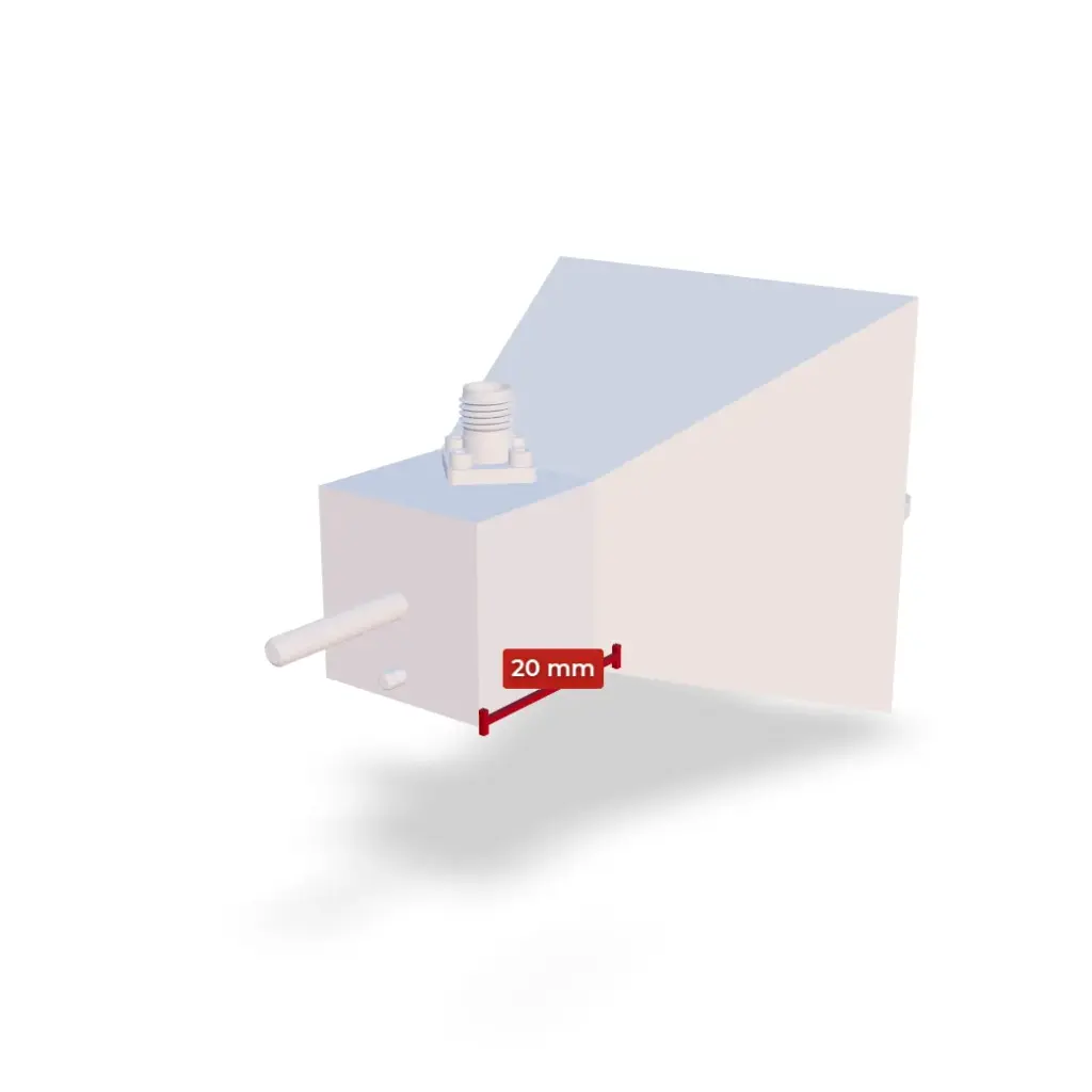
QRH40 · 3D model · drag to rotate

Antenna range

Where your reference horn sets the result

When you measure the gain of an antenna or the EIRP of a module by substitution, an error in your reference horn’s gain passes into the result dB for dB.

The gain you enter should therefore be the one measured on your own unit, and we can deliver it as data instead of a catalog curve. Dual polarized horns receive both polarizations on two ports without rotating the antenna. If your institute calibrates antennas itself, our horns give you consistent artefacts: every unit is machined and plated to the same drawings in our own workshop and measured before it ships.

Use context

Anechoic chamber

Environment

Gain transfer, OTA

Activity

Reference gain

Key quantity

Antenna measurements
RF SPIN calibration laboratory with an antenna in the anechoic chamber
EMC and radio testing

Where the antenna factor is part of the result

In an accredited EMC or radio test lab, the antenna factor enters every radiated emission result, and your assessor will ask how it was obtained.

Our calibration lab is accredited by the Czech Accreditation Institute (ČIA, lab No. 2433) to ISO/IEC 17025 for gain, antenna factor and reflection coefficient from 500 MHz to 40 GHz. It uses the three-antenna method of ANSI C63.5 at 3 m or SAE ARP 958E at 1 m, so you can choose the antenna factor for a 3 m or a 1 m setup. Our certificates are recognized as equivalent under the EA MLA and the Global ACI MRA (formerly ILAC MRA).

Use context

EMC chamber, test site

Environment

Radiated emissions

Activity

Antenna factor, 3 m or 1 m

Key quantity

Accredited antenna calibration
RF SPIN antenna with a custom radome deployed outdoors
Observatory site

Where a spectrum reading must become a field strength

RFI surveys and site monitoring convert a spectrum analyzer reading into field strength, so the antenna factor of the horn on the mast sets the answer.

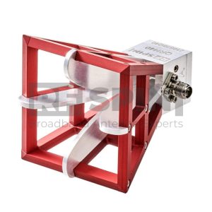
Our EMC Antennas start at 30 MHz with a biconical and at 200 MHz with log-periodics, double ridged horns reach down to 100 MHz, and quad ridged horns add the second polarization from 300 MHz. Several ridged horns also come with a weatherproof radome for outdoor use. Where antennas must act as one, as in interferometry, matched batches keep every unit inside a guaranteed amplitude and phase window: gain differences of 0.3 dB or less, VSWR differences of 0.5 or less.

Use context

Observatory site

Environment

RFI surveys

Activity

Antenna factor, unit match

Key quantity

Outdoor Antennas
Precision-machined RF component from the RF SPIN facility
Experiment hall

Where the band, flange or mount is your own

Beam diagnostics, plasma reflectometry and FEL test benches each set their own band, beam width, flange or mount.

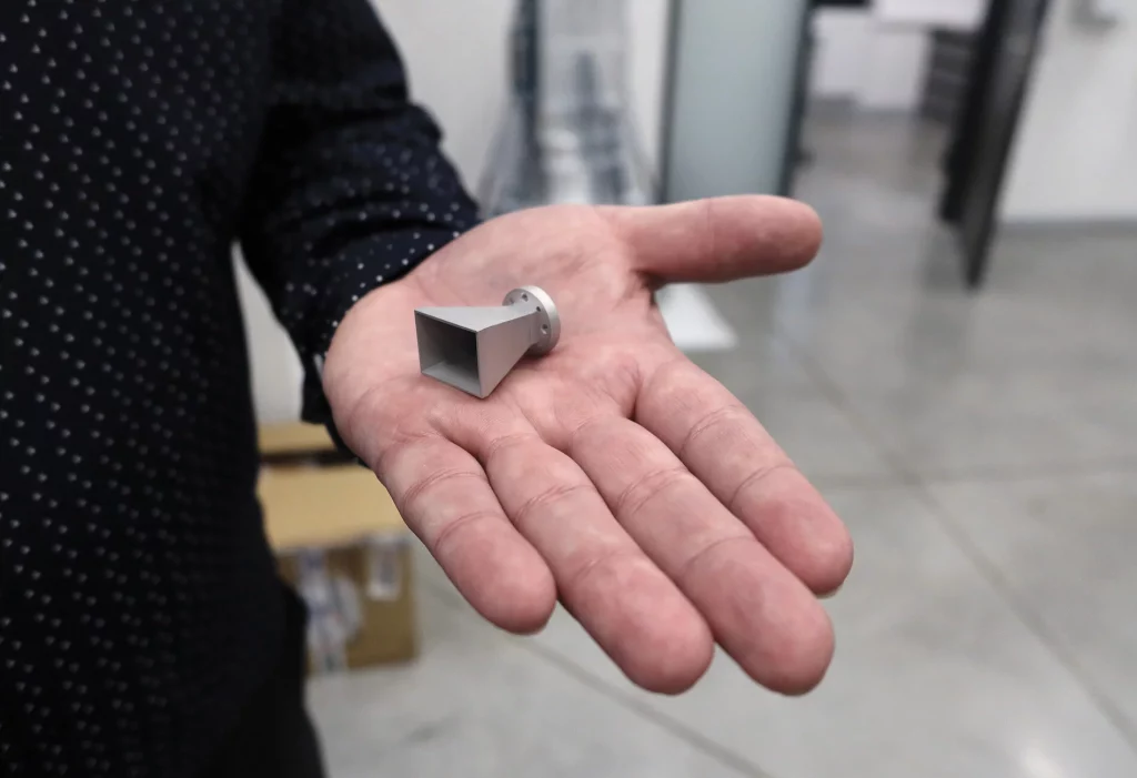
Pyramidal horns up to 140 GHz and waveguide-to-coax adapters up to 110 GHz cover many diagnostic bands from the catalog. Where the catalog stops, you bring a requirement, a sketch or a CAD model, and our engineers turn it into hardware from our own workshop. The same engineers and CNC machines in Nová Paka also make custom metal and plastic parts for experiments and lab equipment.

Use context

Accelerator, fusion, FEL

Environment

Beam, plasma diagnostics

Activity

Band, flange, mount

Key quantity

Custom RF Solutions

Featured products

The horns these settings call for

Five of these six are among the most popular antennas with research labs. The sixth covers the waveguide bands up to 140 GHz.

QRH40 antenna
Antenna range · Dual polarized

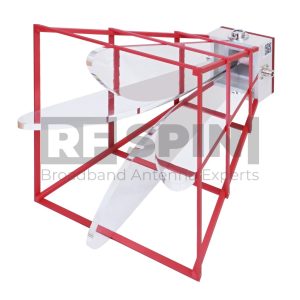
QRH40

4–40 GHz · dual polarized · 6–16 dBi

A reference and probe horn for antenna and module tests across the 4 to 40 GHz span.

28 dB port isolation

K (2.92 mm) connector, 68 g

QRH40C: the same horn with a removable lens, 6–22 dBi

View product
DRH110 antenna
Antenna range · mm-wave

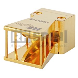
DRH110

14–110 GHz · single polarized · 1.0 mm connector

One coaxial horn across roughly six waveguide bands, so a mm-wave sweep runs without band changes.

6.5–18.5 dBi

22 g on the positioner

DRH1067 covers 10–67 GHz in the same family

View product
DRH40 antenna
EMC test room · Single polarized

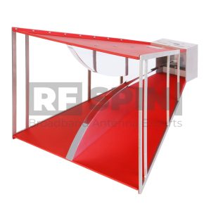
DRH40

4–40 GHz · single polarized · 75 g

A light horn for radiated emission tests above 4 GHz, listed under EMC Antennas as well.

VSWR 1.25 average

Antenna factor 35–47 dB/m

Available with ACCREDITED calibration across its band

View product
DRH370 antenna
Observatory site · Low band

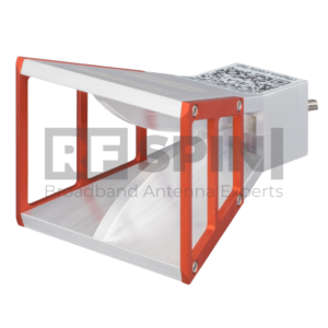
DRH370

370 MHz–6 GHz · single polarized · VSWR 1.2 average

A wideband horn for radio monitoring and emission measurements from UHF to 6 GHz, with its antenna factor on the datasheet.

3.5–16 dBi

Antenna factor 17–33 dB/m

600 W CW

View product
QRH400 antenna
Observatory site · Dual polarized

QRH400

400 MHz–6 GHz · dual polarized · 500 W CW

Both polarizations from 400 MHz to 6 GHz in one horn, designed for large anechoic chambers.

4–15 dBi

32 dB port isolation

QRH400R with radome under Outdoor Antennas

View product
H-A140-W25 antenna
Experiment hall · Waveguide

H-A140-W25

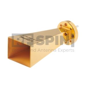
90–140 GHz · pyramidal horn · 24–26 dBi

A waveguide horn with a flat gain of about 25 dBi for diagnostics at the top of our frequency range.

WR-8 waveguide, UG-387/U flange

VSWR 1.1 average

19–21 dBi version: H-A140-W20

View product

Most models in both ridged horn families are listed in stock and ship in 2 days; the rest are made on demand in 4 to 8 weeks.

How we work

What stays the same in every setting

Whichever room and whichever model, three things come with the antenna.

In house

Made by our own people

Design and simulation in Prague; CNC machining, galvanic plating, hand assembly and measurement in Nová Paka. RF-critical tolerances are flagged at handover, not discovered later, and the plating process parameters are ours, not a subcontractor’s.

In-house production
Measured

A record for every unit

Every antenna is measured before it ships: VSWR, gain, radiation patterns, cross-polarization, port isolation and antenna factor. A QR code and a four-character token open the unit’s entry in the RF SPIN Antenna Portal.

Browse the demo entry
Data tiers

As much data as the work needs

ESSENTIAL brings typical curves and a factory test certificate. PLUS brings your unit’s measured VSWR, gain, antenna factor and port isolation in XLSX, CSV, JSON, XML, Touchstone .s1p or via REST API. ACCREDITED brings a calibration from our lab.

Compare data tiers

References

Institutes that work with our antennas

These are some of the research institutes across Europe that work with our antennas, from national metrology to radio astronomy.

Contact

Tell us your setting and your band

Which room, which band, which polarization, and what the antenna has to do there.

We reply within one working day. Your details stay with our engineering team.